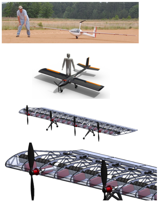
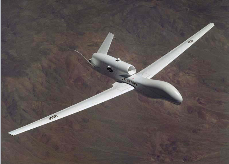
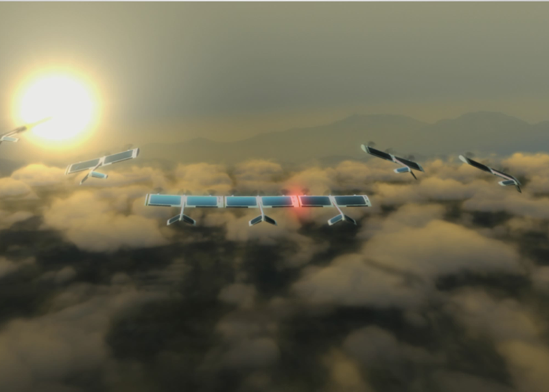
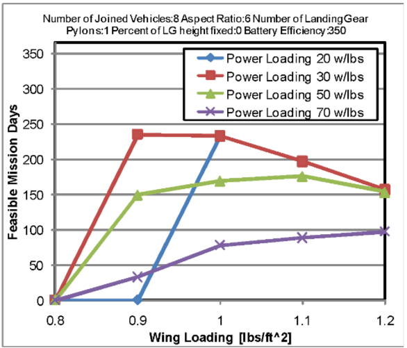
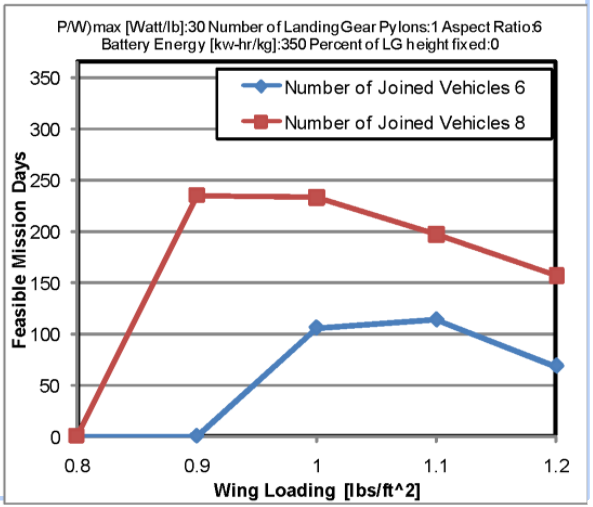
Maximum 48 Hours Endurance

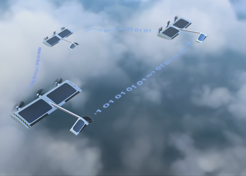
Potentially Unlimited Endurance
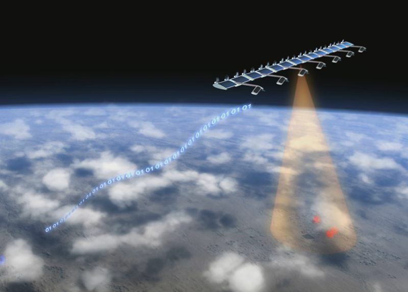
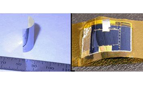
Emcore IMM-3J
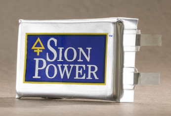
Lithium Sulfur Cell
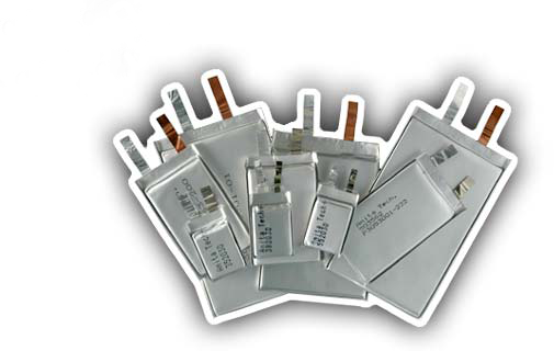
Lithium Polymer Cell
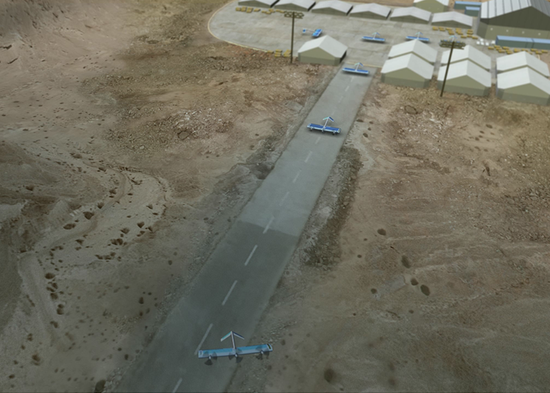
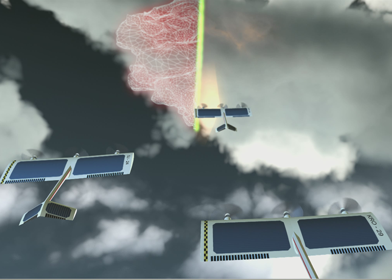
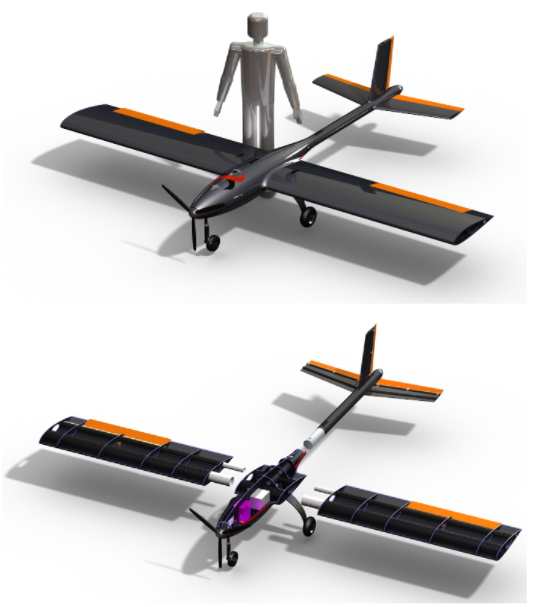
Evaluate the high risk technologies
- Demonstrate the integration of local proximity sensor technology in a flight environment
- Achieve autonomous close formation flight maneuvers with two vehicles
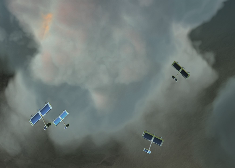
Reduced risk considerations
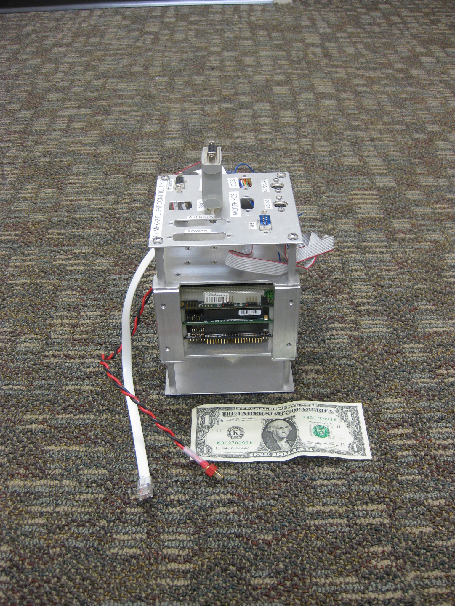
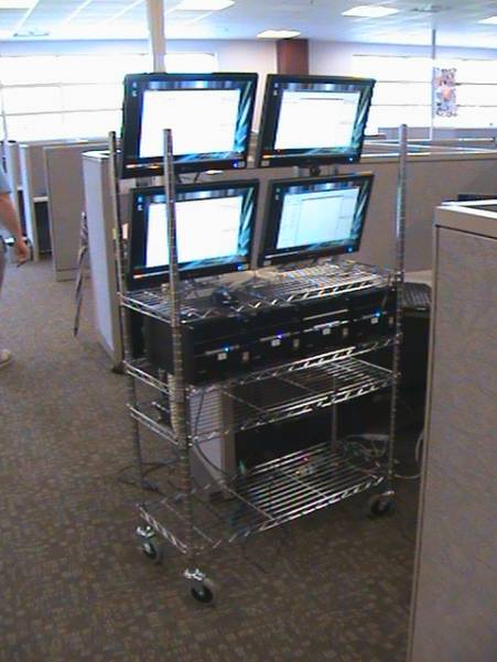
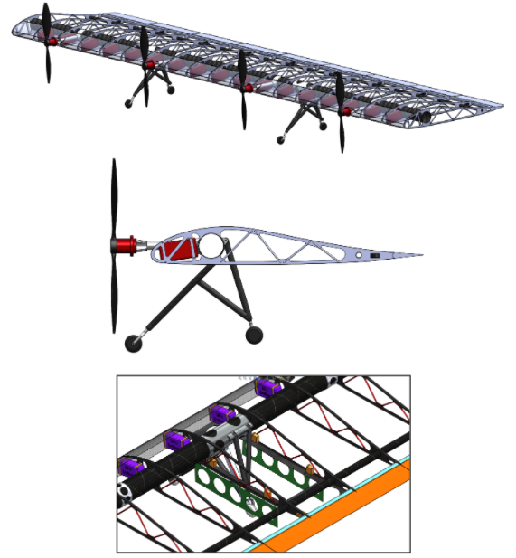
- Use proven commercial off-the-shelf components, including the vehicles and autopilot system
- The flight maneuvering, speed, and performance objectives are minimal.
Desired outcome from flight tests
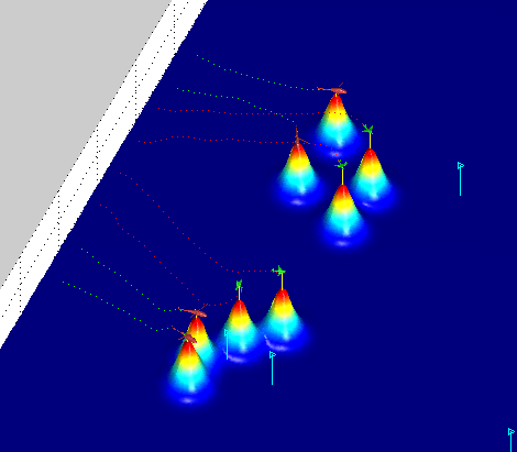
- Computer-controlled flight maneuvers with separations of less than one wingspan using onboard sensor augmentation.
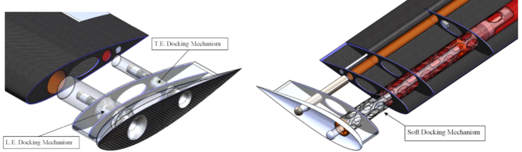
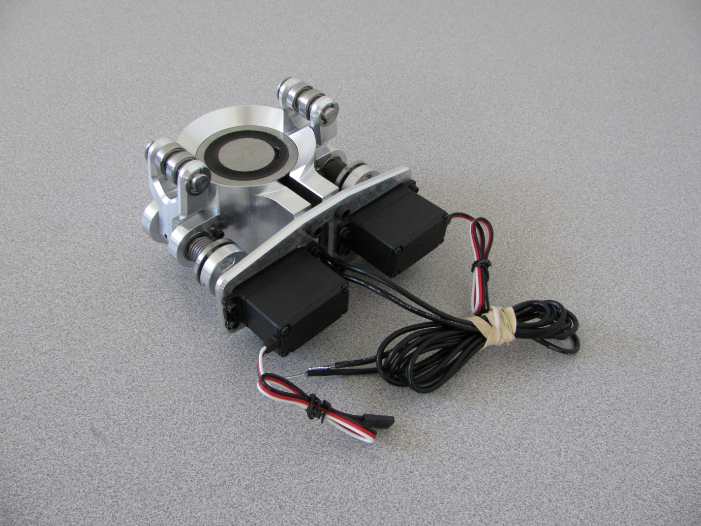
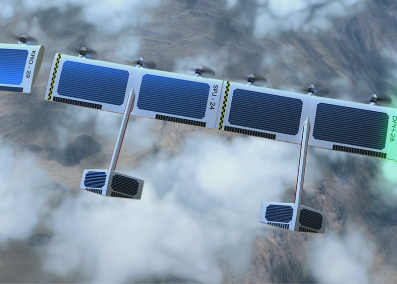
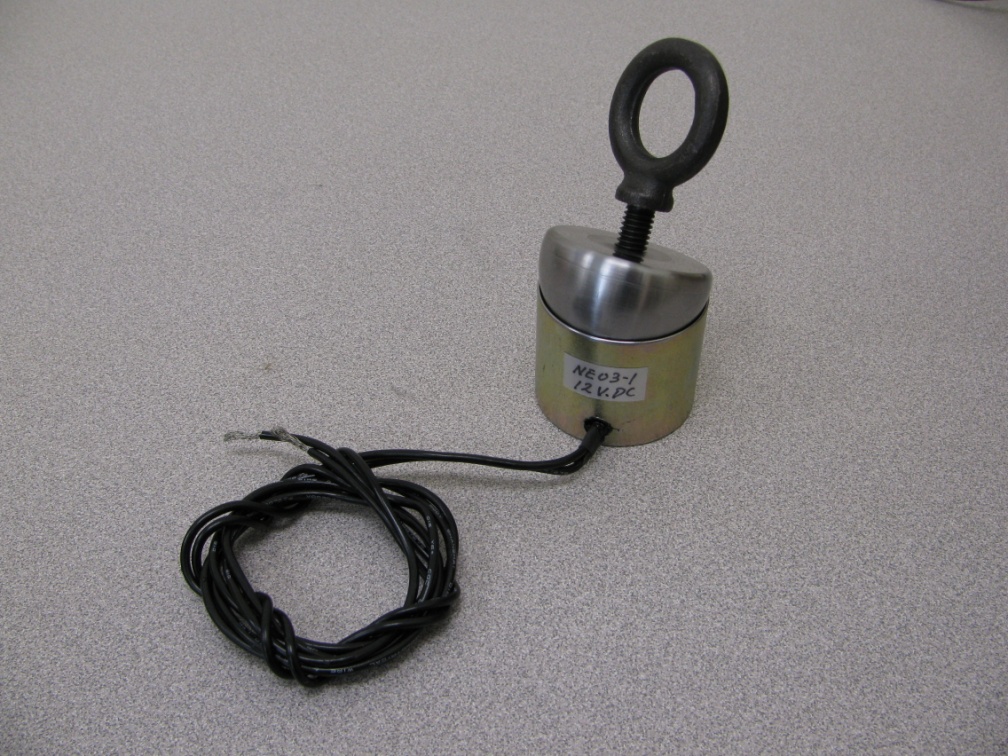
Electromagnet / Mechanical Plug Hard Dock
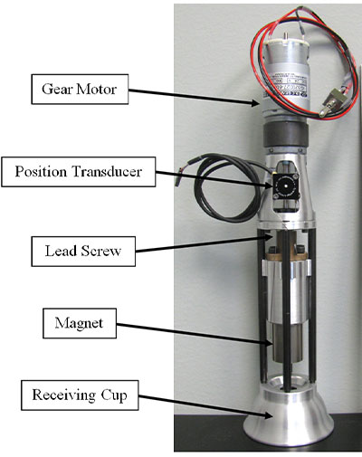
Permanent Magnet (Ball and Socket/Plug) Soft/Hard Dock
Electromagnet (Ball and Socket) Soft/Hard Dock